
The following article will describe the GPX Stream installation process.
This article is available as a video guide by clicking here or at the bottom of this page.
Before you begin... We recommend following our SIM Card installation steps and inserting the SIM card in your modem before mounting the system.
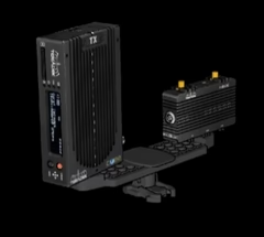
Mounting the 7GX Encoder and modem
In most cases, your GPX Stream system came included with a custom double mount, and a roll bar clamp.
The 7GX encoder and modem are mounted on the screws of the double mount, and connected to the roll bar clamp. If the device are not already mounted on the double mount, attach the devices to each screw on the double mount, paying attention to the ideal mounting and space requirements inside the vehicle.
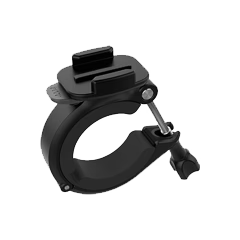
With the devices mounted, unscrew the thumb screw from the roll bar mount, and release the lower part by tilting the screw upwards, releasing it from the bottom part.
Ensure the rubber vibration dampener of the mount does not fall off.
Place the mount around a roll bar, tilt the screw downward to clamp down the bottom part, and twist the thumb screw until the mount is tightly secured to the roll bar.
With the roll bar mount in place, lift the rubber lock from the clip at the bottom of the double mount, and slide the clip in the slot at the top of the roll bar mount.
Once the clip is securely fastened, press the rubber lock down to prevent accidental release.
Wiring
In most cases, your GPX Stream systems comes pre-assembled.
If cables need to be disconnected for installation, please carefully note the connection port for each cable to ensure it is reconnected in the correct port.
When wiring the system, we recommend the use of Velcro cable ties to prevent excessive strain or pinching of cable which may cause internal damage to the wires.
If zip-ties are used, please ensure they are not overly tightened!
Mounting Antennas
With your devices securely mounted, start by mounting the antennas.
Antennas can be mounted with the provided dual-sided tape (if applicable) or using dual-lock.
With the antennas mounted on or inside the vehicle, carefully route the cables ensuring they will not be pinched by any moving parts such as doors or other body panels.
If your kit contains a Node 1 modem (two antennas terminals), please see the Node 1 page.
For Node 2 modems, please see the Node 2 page.
Important Notes for all Antennas
To prevent interference, antennas should always be mounted:
At least 6 inches from any other antennas (GPS, radio, telemetry,...)
As far as possible from any in-car radios, and any other RF-emitting device
Always mount antennas facing up towards the sky
Avoid mounting antennas on metal surfaces when possible
Please note GPX offers a variety of antennas - make sure to follow the instructions specific to the antenna in your kit.
Antennas with two LTE leads or Antennas with a single LTE lead and a GPS lead
These antennas are not weather-proof and must be mounted inside the vehicle.
Antennas with a single lead
These antennas are weather-resistant, and should be mounted on the exterior of the vehicle for best performance.
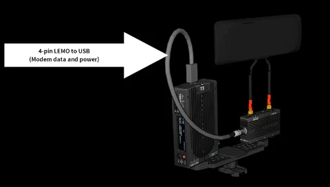
Modem Power and Data cable
The next step is to connect the modem to the video encoder.
This is done using the short LEMO to USB cable.
Start by connecting the LEMO connector to your modem, then connect the USB to the top of your video encoder.
Make sure the USB connector is securely pushed all the way in to its receiving socket!
An improper connection of the USB cable may lead to the modem receiving power, but not transmitting data.
The Node 1 Modem uses a 4-pin LEMO to USB, while the Node 2 uses a 5-pin LEMO to USB. These are not interchangeable!
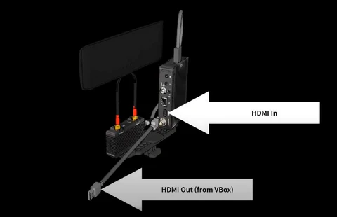
HDMI Cable
The next step is to connect the HDMI cable to your video system (VBOX, camera, etc).
Connect either end of the HDMI cable to the 7GX encoder, and the other end to the VBOX or camera.
If you're using the RaceLogic VBOX system, please ensure the HDMI Output settings are correct, otherwise the VBOX will not output video over HDMI by default! To do so, visit the RaceLogic support page here
GPX strongly recommends the use of the included slim HDMI cable.
While other cables may work, the additional weight and lack of flexibility of standard HDMI cables generally lead to a more difficult installation.
HDMI cables will also be damaged sooner due to the additional forces applied to heavier cables by the g-forces generated while on track.
Power Cables
7GX Power
The final step is to connect the 7GX encoder power cable.
The 7GX is powered by a succession of two cables: the 7GX power cable, and a power loom.
GPX offer multiple power looms, but this guide will focus on our most popular option, the VBOX power splitter.
Regardless of which power loom option you have chosen, the 7GX encoder is always powered by the same cable. This cable is a short 2-pin DTM (female) connector to a 2-pin LEMO.
Extreme caution must be exercised with the 2-pin LEMO connectors included with your system.
THE POWER PINOUT FOR THE VBOX AND THE 7GX SYSTEM ARE INVERSED.
Plugging in a connector intended for the VBOX into the 7GX will lead to permanent damage.
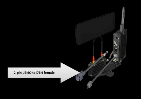
Always connect the 2-pin DTM (female) to 2-pin LEMO connector into your 7GX encoder first to avoid the issue mentioned above.
Once this cable is connected, you can connect the power loom.
All GPX power looms are built with a 2-pin DTM connector on one end, that will attach to the 7GX power cable.
VBOX Power Splitter
The VBOX power splitter has a 2-pin DTM (male) connector, a 2-pin LEMO connector (female), and a 2-pin LEMO connector (male).
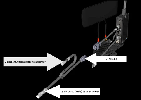
To provide power to the 7GX through the VBOX, first disconnect the existing power cable from the VBOX.
Connect the cable you just unplugged to the female LEMO connector on the VBOX Power splitter.
Next, take the male LEMO connector from the VBOX Power splitter and connect it to the VBOX power port.
Finally, connect the male DTM connector from the VBOX Power splitter to the female DTM connector from the 7GX power cable.
For other power looms provided by GPX (unterminated, 488 Challenge, 12V,...), simply connect the 2-pin DTM (male) connector of the power loom to the 2-pin DTM (female) connector of the 7GX power cable.
The other end of the power loom will either be connected to a specialized connector or directly to battery terminals.
In the case of the Ferrari 488 Challenge power loom, the specialized connector can be found along the wiring loom of the vehicle on the passenger side, usually near the fire extinguisher bottle. Please note this connector might be hidden underneath the power loom, but is always there!